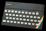
The Sinclair Spectrum was a phenomenally
successful microcomputer. It spawned the home computing revolution
and is the reason why Great Britain (in my humble opinion :)
is the home of leading edge game development today. All computers
have certain features in common. They all have a CPU (Central
Processing Unit) that is responsible for carrying out the instructions
within your program. They all have memory to hold your program
and data, and they all have input/output devices to allow communication.
Memory, from a CPU point of view, is a collection of numbered
locations, each one capable of holding data. The location is
called the address. The data stored is in the form of a bit-pattern
(a one or a zero). The Spectrum can store a pattern composed
of 8 bits in every address. Binary numbers are a common method
of representing data in a bit-pattern. From right to left each
bit-pattern holds a values increasing by the power of two, i.e.
bits 0 to 7 represent 1,2,4,8,16,32,64,128 respectively.
These 8 bits collectively are called a byte and it can be
seen that they can hold a value in the range 0 to 255. Each
address is formed of two bytes (16 bits) and can store the
numbers in the range 0 to 65535. Which as will be seen later
is the size of memory in a Sinclair Spectrum with 48k of memory.
From a hardware point of view bits are nothing more than high
and low voltages.
The Spectrum has a number of buses that perform the critical
task of supplying data to/from the various components of the
computer. A bus is no more than a group of wires used to transport
a bit-pattern, in the form of voltage levels, from one part
of the computer to another. Each wire in the bus carries the
state of one bit. The Spectrum has two buses:
-
The Address Bus transfers 16bit data from the CPU to
memory. The Data bus transfers 8bit data to/from various
parts of the computer. Note that the Address Bus is uni-directional
whereas the Data Bus is bi-directional.
-
The Control Bus connects the CPU to the rest of the machine.
The control bus is used to transport synchronisation data,
state information, etc.
The video display is maintained by the ULA which displays
the information stored in a fixed area of memory - the video
memory - to produce a fixed format (256 dots by 192 dots -
or 32 characters per line for 24 rows).
The Spectrum has (or rather had, at the time) a sophisticated
and general method of dealing with different I/O devices,
based on Streams and Channels.
|
 48k Spectrum